
For many homeowners, installing a water-heated floor on a concrete base is a popular choice. The home is consistently warm and comfortable thanks to this kind of heating system. However, in order to achieve maximum performance and longevity, it is imperative to comprehend the various layers involved in its construction.
As the foundation, a concrete slab is used to start the process. Several layers are added above this slab to provide effective insulation and heat distribution. Every layer, from thermal insulation to moisture protection, serves a distinct purpose and is essential to the heated floor system’s overall performance.
Installing these layers correctly not only optimizes energy efficiency but also averts potential problems like moisture damage and heat loss. Understanding the specifications and layout of a water heated floor cake on concrete will help you make well-informed decisions and get the best results for your home heating needs, whether you’re planning a new construction or renovation.
A concrete water-heated floor system is made up of multiple key layers, each with unique specifications to guarantee longevity and effectiveness. You will gain a clear understanding of how to achieve maximum performance and comfort in your home by reading this article, which will explain the design of these layers, from insulation to the final flooring.
- Requirements
- Maximum and minimum thickness
- Layers and requirements for them
- Concrete base
- Waterproofing
- Reflective insulation
- Reinforced mesh
- Floor heating pipes
- Wet concrete screed
- Finish coating
- Why is it important to know the nuances?
- Useful video
- Video on the topic
- Warm floors without extra expenses.
- MINIMUM WARM FLOOR PIE
- 🔥 1. OPTIMAL WARM FLOOR pie! DIY water heated floor. My heated floor is on the ground
Requirements
The design and functional parameters as well as regulatory documents listed below determine the requirements for a water-heated floor placed over concrete:
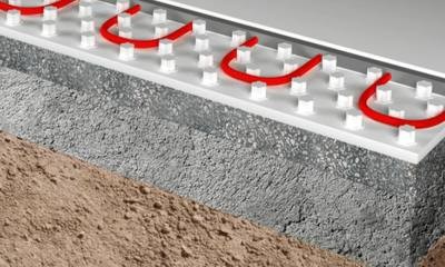
- Design requirements:
- The thickness of the protective layer of the screed from the top and bottom edges, to the reinforcement elements and the top of pipe communications, must be at least 10 – 15 mm.
- The distance between the water heated floor pipes and the reinforcing flat frame must be at least 20 mm.
- Under the screed, if there are water pipe communications with a liquid coolant, insulation made of polystyrene foam with a thickness of 50 mm must be installed, as well as waterproofing materials that prevent leakage in case of an accident.
- Space-planning requirements:
- The upper level of the screed must meet the requirements of the detailed design.
- The clear height of the premises must not be lower than the minimum established parameter, according to current standards.
- When installing a screed, the maximum height of the threshold between adjacent rooms should not exceed 10 – 20 mm.
- Thermal parameters:
- The diameter of the pipe communications must ensure unimpeded circulation of the liquid coolant.
- The heating energy must be evenly distributed in the concrete screed structure, which requires the installation of a layer of a certain thickness above the pipes.
- To achieve maximum heat transfer and energy efficiency of the premises, pipes in the water heated floor, laid in the body of the screed, must be spaced from the edge of the finished floor covering no more than the maximum permissible value.
- Regulatory Requirements:
- SP 29.13330.201.1. Floors.
- SP 71.13330.2017. Insulating and finishing coatings.
- SP 54.13330.2016. Residential multi-apartment buildings.
- SP 63.13330.2018. Concrete and reinforced concrete structures.
- GOST 27006-86. Concrete. Squad selection rules.
- GOST 13087-2018. Concrete. Methods for determining abrasion.
- GOST 30459-2008. Additives for concrete and mortars.
A heat engineering calculation is performed, the temperature of the liquid coolant, the diameter of the pipe communications, and the development of architectural drawings that show the floor covering pie while accounting for all layers and their power are all based on the aforementioned requirements.
Maximum and minimum thickness
In compliance with the aforementioned specifications, the thickness of each layer and the structure as a whole may be assigned within the following ranges when planning and building a screed pie, keeping in mind the placement of pipe communications for a water-heated floor:
- The minimum thickness of the pie, taking into account coating waterproofing, insulation with a capacity of 30 mm and a concrete structure with a minimum diameter of pipe communications of 15 mm, can be 80 – 90 mm.
- The optimal thickness of a screed with a water-heated floor, with a capacity of 50 mm polystyrene plates, reinforcement and pipes with a diameter of 20 mm, is 100 – 110 mm.
- The maximum thickness of the cake, taking into account all layers for a standard floor height in the range of 3000 – 3300 mm, should not exceed 120 – 140 mm.
It should be remembered that the screed cannot be thinner than what is specified above because doing so could result in both a large loss of heat and insufficient strength for the concrete structure.
The screed can have a large thickness, but this solution is unique and requires specific calculations if the premises have increased requirements for ensuring energy efficiency, floor slabs, ledge elements are designed for all attached stoic constant and temporary loads, and the ceiling height in the light allows you to arrange more powerful layers.
Layers and requirements for them
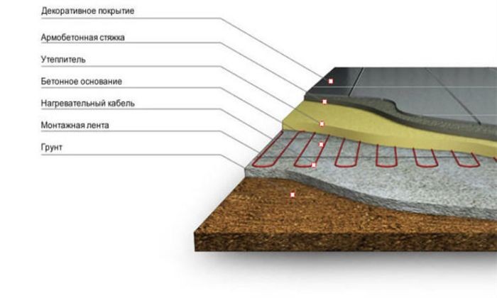
The screed’s design, given that the water floor pipeline communications contain a specific set of structural components. In turn, every one of these layers has distinct technical properties, measurements, and is made of unique materials that guarantee the structure’s overall dependability and durability in addition to increased mechanical strength. If a heating system with a closed circulation loop and liquid coolant is installed in it, each layer of the floor screed pie is explained in detail below.
Concrete base
Synopsis:
- The base is a floor slab above the lower floor, or an insulated monolithic reinforced concrete foundation structure, in the absence of any rooms below level 0.000.
- The base serves as a supporting structure for the installation of all overlying layers of screed, as well as insulation elements and engineering equipment.
- The base can be made of monolithic concrete, cement-sand mortar on beams and asbestos-cement sheets, prefabricated concrete products and other types of load-bearing structures.
Conditions:
- No traces of visible mechanical damage, cracks, cavities, chips.
- The maximum value of differences in elevations is up to 5 – 10 mm.
- Sufficient load-bearing capacity for constructing a full screed pie with the subsequent application of all operational static or dynamic loads.
- Conformity of the actual deflection in the loaded state with the maximum permissible standard vertical movements.
- Slight physical wear of the span structure or foundation slab on the ground.
When installing reinforced concrete floor slabs, their thickness varies from 160 to 250 mm, prefabricated hollow-core slabs from 220 mm, and products made using profiled sheets from 140 mm or more, taking into account the ribs of galvanized non-removable formwork. This depends on the content of the working design.
Features:
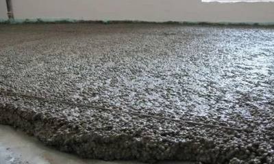
- Concrete class – depends on the static calculation of the reinforced concrete span structure, as a rule, from B20 – B25 and higher.
- Frost resistance – from F75 – F100.
- Waterproof rating – from W2 – W
- Density of LH structure – 2400 – 2500 kg/m 3 .
- Abrasion – no more than 1.6 g/cm2 .
Resources:
- ready-mixed concrete of the selected class;
- reinforced rod reinforcement with periodic profile A500s.
Waterproofing
Synopsis:
- Installed as coating, lining or penetrating waterproofing.
- In case of an increased risk of flooding of adjacent rooms, a combined design of waterproofing the floor slab is recommended.
- May consist of bitumen or polymer materials.
- Ensures complete tightness of the structure in case of depressurization of the circulation ring of underfloor heating pipes.
Conditions:
- No toxic polymer components.
- Resistance to temperature changes.
- Good elasticity – when bent, the material should not break or crack.
- Complete sealing of the layer after its installation, in strict accordance with technological requirements.
- The melting point should not be lower than +80 o C.
- The material must remain plastic up to a temperature of – 15 – 25 o C.
- Good coverage of hard surfaces with liquid mastic without the formation of bubbles or uncovered areas.
Density:
- Coating waterproofing – from 2 to 3 mm.
- Pasted waterproofing – from 4 to 6 mm.
- Polymer waterproofing membrane – from 1 to 3 – 4 mm.
Features:
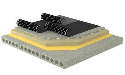
- The maximum force of the gap is from 0.6 – 0.9 kN.
- Flexibility on steel beams with a radius of up to 25 mm – 15 – 25 o C.
- The recommended average temperature resistance of bitumen binder is from 80 to 100 o C.
- Maximum permissible tensile force, without loss of shape – up to 0.2 – 0.3 kN.
- Water absorption of bitumen material – ranging from 0.5% to 1%.
- Resistance to impact loads, bursting limit – from 1.5 to 2.5 kN.
Resources:
- Fiberglass used as a base.
- 2 layers of modified bitumen.
- Protective polymer film that prevents material gluing.
- For bitumen mastic – hardeners and solvents that ensure the required state of aggregation of the material.
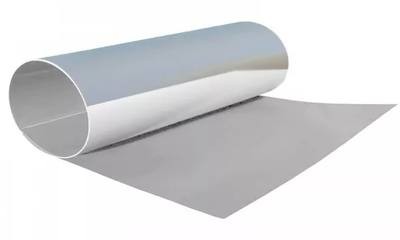
Reflective insulation
Synopsis:
- Can be supplied in the form of a simple metallized sheet, rolled into a roll, or has a porous base, which provides additional resistance to heat transfer.
- It is laid out strictly under the pipes of the warm floor, the insulation is designed to reflect thermal energy and prevent its penetration into adjacent vertical rooms.
- Plays the role of additional waterproofing due to the impenetrable structure.
Conditions:
- presence of metallized coating;
- porous base;
- preventing rupture;
- resistance against dynamic and static loads, including point and shock-impulse loads, absence of flammable polymers in the membrane composition.
Density:
- Baseless – from 0.5 to 1 mm.
- With a polymer porous base – up to 10 – 15 mm.
Features:
- Mechanical strength of the material – up to 15 – 25 MPa.
- Heat transfer resistance – from 0.03 to 0.045 W/m °C.
- Volumetric weight, taking into account the porous substrate – from 80 to 150 kg/m3 .
- Membrane vapor permeability index – from 0.04 to 0.06 mg/MPa.
Resources:
- Polyvinyl chloride base.
- Aluminium foil.
- Polyurethane adhesive viscous substance, for gluing dissimilar materials.
Reinforced mesh
Synopsis:
- It is laid in the structure in the form of a finished mantry or road grid, or in the form of a flat knitted frame, consisting of separate rods with a periodic profile.
- Provides increased load-bearing capacity when concrete works in tension.
- The mesh is laid only in the lower zone of the concrete screed.
- Allows a concrete structure to work in span over an elastic base made of polystyrene foam insulation.
Conditions:
- Mechanical strength, in accordance with GOST requirements.
- Deformation resistance – when bending, the mesh should not crack due to its plastic properties.
- Minimum amount of corrosion.
- Periodic profile of rods to improve compression during hardening of screed concrete.
- Reinforcing steel class – A500s, or BP-I.
- Lack of paint and varnish coating and a layer of contamination, which can affect the adhesion strength of concrete and steel.
Density:
- For masonry mesh, the diameter of the rod is up to 3 mm, the total thickness of the mesh is up to 6 mm.
- For road mesh – from 5 to 6 mm, total mesh thickness – from 10 to 12 mm.
- For reinforcing individual rods laid in the screed by means of a flat frame knit – from 6 to 10 mm, the total thickness of the frame, taking into account the crossroads of the reinforcement – from 12 to 20 mm.
Features:
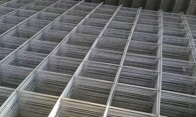
- Grid cell size – from 50 x 50 to 200 x 200 mm.
- Steel class – A500s, VR-I.
- Mechanical compressive strength – up to 250 – 300 MPa.
- Mechanical tensile strength – up to 400 – 500 MPa.
- Limit deviation from nominal dimensions – from 1% to 3%.
- Relative elongation during rod stretching – up to 25%, until the material yield plateau is formed.
- Modulus of elasticity of the material – up to 20 thousand. MPa.
Resources:
- structural steel 3;
- manufactured at specialized steel foundries with subsequent molding of the finished product;
When making a mesh, the wire is drawn, cut to size, and then fixed using contact spot welding.
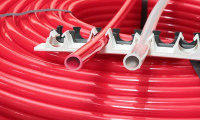
Floor heating pipes
Synopsis:
- Made of reinforced polypropylene, black or stainless steel.
- Laid into the structure, according to the heat engineering calculation.
- A coolant circulates through the warm floor pipes, which gives thermal energy to the room.
- The pipes are connected to the main risers at the supply and return, forming a closed, hermetically sealed circulation ring.
Conditions:
- Polymer or steel water pipes must be designed for constant circulation of liquid coolant heated to 60 – 80 o C.
- HDPE pipes must be reinforced with foil screen.
- The internal diameter of the pipes must fully satisfy hydraulic calculations.
- All pipe joints must be made only with welded joints, through crimp couplings, to maintain tightness under pressure throughout the entire service life.
- Pipes must be laid in the structure with the required spacing, without exceeding the permissible bending radius of the product.
- It is recommended to carry out the layout according to standard schemes, according to SP.
- All pipe communications must be fixed with special loop clamps.
Density:
- The outer diameter of steel pipes is from 15 to 25 mm.
- HDPE pipes, due to their thick walls, can have a diameter of up to 32 mm.
Features:
- Consumption at operating pressure – not less than 0.25 – 0.35 t/h.
- Tensile strength of the polymer structure wall – up to 25 – 30 kgf/cm 2 .
- Maximum permissible operating pressure inside the pipe – up to 0.6 – 1.1 kgf/cm 2 .
- The thickness of the steel reinforcement of the HDPE pipe is up to 0.3 – 0.5 mm.
Resources:
- special polyethylene;
- withstands high pressure and temperature;
- reinforcing screen – aluminum alloys;
- when choosing steel pipes – structural steel 3, or brass.
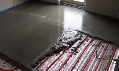
Wet concrete screed
Synopsis:
- Made from concrete of the required class.
- Serves as a protective layer for pipe communications of a water-heated floor, as well as a supporting base for the installation of a finishing coating.
- A reinforcement mesh is installed in the body of the screed, which increases the load-bearing capacity of the structure, as well as water-heated floor pipes.
- Poured in one step, between galvanized steel beacons, or using a laser level.
Conditions:
- Mechanical strength.
- Crack resistance.
- Wear resistance, increased abrasion resistance.
- Minimum porosity coefficient, which is achieved by using fine sand as a filler and moving mixture.
- Increased rolled water resistance.
- Resistance against temperature changes.
- Shock resistance.
- Increased hardness of the finishing surface due to the presence of modifying additives containing polymers in the concrete composition.
- The absence of chips, cavities, non-vibrated areas, areas with delamination and other mechanical defects that may interfere with the installation of the finishing floor covering.
Density:
- For pipe diameters up to 15 mm and no reinforcement – up to 70 mm.
- With pipe diameters up to 15 mm, with reinforcement with road mesh – up to 80 – 90 mm.
- With pipe diameters up to 25 mm and reinforcement with road mesh – up to 100 – 120 mm.
- With a pipe diameter of 25 mm or more, reinforced with individual rods tied into a flat frame – from 120 – 140 mm or more.
Features:
- Cement grade – from M400 and more.
- Fine aggregate – quartz or washed river sand with a fraction of 2.5 to 4 mm.
- Coarse aggregate (if necessary, if the material is provided for in the working design) – crushed granite stone with crushed edges, fraction 10 – 20 mm.
- The final class of concrete for compression is no less than B15 – B20.
- Design grade for frost resistance – from F50 above.
- Grade of concrete screed for water resistance – from W4 or more.
- Availability of plasticizers – when concreting in the cold season – antifreeze additives, if it is necessary to increase the setting period – plasticizers, to ensure volumetric structural waterproofing – water repellents.
- To increase deformability properties, other modifying additives may also be required.
Resources:
- Cement – from 15% to 25%.
- Sand – from 50% to 75%, depending on the brand of screed, as well as the need to add coarse aggregate to the solution.
- Crushed stone – from 0% to 25%.
- Water – from 90 to 120 l/m 3, depending on the required mobility of the liquid solution – P3 or P4.
- The total amount of modifying additives is no more than 4%.
Finish coating
Synopsis:
- The type of coating depends on the design project of a particular room, as well as on the characteristics of its operation.
- The coating can be arranged “in a lock”, or using special adhesive compounds.
- As a rule, all types of finishing floor coverings require the installation of an additional soundproofing underlay made of natural or synthetic materials.
- All floor finishes are designed to withstand operational loads from furniture items, as well as the weight of people who use the premises.
Conditions:
- Increased wear resistance, which guarantees the durability of the material.
- High quality finishing coating.
- Fire resistance, fire safety.
- Easy to clean, wet cleaning of the coating.
- Compliance with the design project of the premises.
- Resistance against aggressive environmental influences, which is especially important for wet rooms with high temperature and humidity conditions.
- Environmental safety – coatings should not contain toxic components that cause allergic reactions or irritation of motor tracts in dependent people.
- Aesthetic appeal.
- Easy to cut and install.
- High degree of adhesion to the base of the concrete screed.
Density:
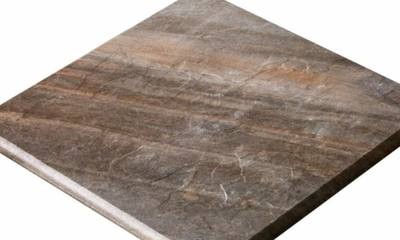
- Porcelain tiles – from 5 mm material thickness, from 3 – 5 mm – adhesive composition.
- High-strength porcelain tiles – from 10 mm – thickness of the finishing material, from 5 mm – thickness of the adhesive layer.
- Technical laminate – from 5 mm – the thickness of the covering polymer material, from 3 – 5 mm – the thickness of the polymer or cork substrate.
- The main laminate for residential apartments and houses – from 7 – 8 mm – lamella size, the size of the covering layer is the same as in the previous case.
- Linoleum – from 3 mm without base, from 5 – 6 mm – on a felt backing.
- Piece parquet – from 10 – 20 mm, based on plywood or hardboard – from 5 mm.
- Self-leveling polymer floor with abrasive inclusions – from 1 – 3 mm.
- Carpeting – depending on the height of the pile – from 5 to 15 mm.
- Film protective coating of the screed, arranged thermostatically – from 1 mm.
Features:
- Water absorption – no more than 3%.
- Frost resistance – from 75 to 150 cycles of temperature changes through zero during the season.
- Material surface strength – from 35 – 50 MPa and above.
- Wear resistance – at least 4 – 5 classes.
- The friction indicator, depending on which the protection of the user’s sole from slipping is determined – no less than R-10.
- Material hardness – no less than 7 – 8 on the Mohs scale.
- Fire resistance – from EI 15 and above.
- Flammability group – not lower than G0 – G1.
- Toxicity index – from T1 and below.
Resources:
- Natural wood (pine, birch, oak, beech, teak) – for piece parquet.
- Wood veneer – for parquet boards or premium laminate.
- Polymer laminated film over MDF, or wood-based – for classic laminate.
- Fired clay raw materials, coated with glaze – for porcelain stoneware
- Polyvinyl chloride – for linoleum and synthetic carpet.
- Natural wool – for natural carpeting.
- Polymer liquid adhesive materials with mineral abrasive inclusions – for self-leveling floors with decorative coating.
Why is it important to know the nuances?
The subtleties of the design of a concrete screed with an integrated water floor should be understood by any property owner or contractor doing maintenance and finishing work on the property. You can accomplish the following advantageous outcomes with the help of this trustworthy information:
- Achieving maximum structural strength.
- Satisfaction of the requirements of applicable standards.
- Compliance with protective layers of concrete structure.
- Sealing heating pipes laid in the body of screeds,
- The device of insulation from polystyrene foams with the desired layer thickness
- Compliance with the volume-planning parameters of the room, taking into account the height of the floor from the clean floor to the ceiling mark.
- Achieving the optimal mechanical strength of the screed laid on top of the elastic insulation, as well as the calculation of the structure in the second group of maximum states, the purpose of the reserve coefficients according to the conditions of operation of the concrete structure of the screed.
- Exclusion of the formation of a step or threshold between adjacent rooms with various floors pies.
- Selection of the necessary components of the concrete mixture.
- Decision -making on the need to arrange vocational, coating or penetrating waterproofing.
- Calculation of the exact number of materials before buying them at a outlet.
Errors in the mixing of ingredients, selection of inferior materials, or lack of any necessary layer in the screed cake may result in premature deterioration of the concrete structure or a reduction in the room’s energy efficiency, both of which will unavoidably lead to higher operating expenses for the facility’s users.
Useful video
Further details regarding the subject matter of the article in the video:
| Layer | Description |
| Subfloor | The base layer, usually concrete, should be clean, level, and dry to ensure good adhesion and performance. |
| Insulation | Placed over the subfloor to prevent heat loss and improve efficiency. Common materials include foam boards or insulation sheets. |
| Underfloor Heating Pipes | These pipes carry warm water and are laid out in a specific pattern to ensure even heat distribution. They must be securely fastened to prevent movement. |
| Heat Distribution Layer | This layer, often made of a special type of screed or thin concrete, helps distribute heat evenly across the floor surface. |
| Finish Layer | The top layer, such as tiles, laminate, or carpet, is installed over the heat distribution layer. It should be compatible with underfloor heating to ensure optimal performance. |
A thorough understanding of every layer in the setup is necessary to create a water-heated floor system that works well on a concrete base. Every part, from the final flooring to the insulation layer, is essential to guaranteeing effective heat distribution and energy conservation.
To stop heat loss and channel warmth upward into the living area, proper insulation is crucial. In addition to providing a sturdy base, the screed layer encloses the heating pipes and uniformly distributes heat throughout the floor. Durability and optimum performance are ensured by selecting the appropriate materials for each layer.
It’s also crucial to install software according to best practices. This entails using a dependable thermostat system, making sure the screed is level, and arranging the heating pipes appropriately. By taking these precautions, you can prolong the flooring system’s lifespan and maintain a comfortable temperature.
Homeowners can create a water-heated floor that increases comfort and conserves energy by comprehending the specifications and layout of each layer. Warm and welcoming interior design can be achieved by devoting time and energy to proper installation.


